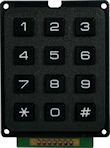
One of the important upgrades from the proto-type is to change the old keypad, the knocked-up version described in this post, to a proper ‘matrix keypad’ (ie with numbered buttons) as seen on the left (Maplins order code: JM09K, £2.99).
The Keypad
The first thing to do is to work out how the matrix keypad is wired. For such a widespread product, there’s a dearth of useful information as to how the thing is to be wired. So, this is my attempt to try and demistify things a little.
 First up, the 7 holes at the bottom of the keypad. These 7 holes needed to have an equivalent 7-pin header attached (or just 7 straighthrough header pins) soldered into them in order to be able to wire the keypad to anything useful. This was my first bit of soldering and there are plenty of guides out there as to how to get started (I used a £30 50W solder station from maplins (order code N78AR). I used a JYK “7 way straight pin header” from rapid electronics (order code: 22-2390) which will be attached the equivalent “7 way crimp housing” (order code: 22-2350).
 Having soldered them on, the next thing to do was to work out which pin on the keypad controlled what. Basically, each of the 7 pins relates to one of the four rows or three columns. It’s just a question of working out which does what. After a bit of testing [see post-script], the results I came out with are shown on the left. So the first pin (pin 1) is wired up to the second column (numbers 2, 5, 8, 0), pin 2 is wired up to the first row (numbers 1, 2, 3) etc.
To put it another way, rows 1 to 4 are controlled by pins 2, 7, 6, and 4 respectively.
 With that information is very straightforward to work out the necessary combinations for any particular number on the keypad. Number 1 connects pin 2 and pin 3. Number 2 connects pin 1 and pin 2. As shown on the right.
The Crimping
The next thing to do is to find a tidy way of wiring up those 7 pins over a short distance to the arduino. (Here the keypad is going to sit on the main left strut of the binocular mirror mount so I need a cable length of about 30cm.)
To try and make sure that everything sat ‘tight’ I used a 7 way pin header and crimp housing. This allows for the keypad to be detached easily from the main wiring and keeps the wires tidy between the keypad and the arduino chip. Crimping proved pretty straightforward once I’d got the right tool. I used this crimp tool from Rapid Electronics (code: 85-0262).

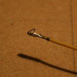
1. On the left are the crimp terminals Iused. I bought this roll from Rapid Electronics (order code 22-1096).

2. To fit the crimp terminal onto the wire, the wire has to be stripped just enough so that bare wire will make a connection with the end part of the terminal, but leaving enough of a shield to be gripped by the first part of the crimp terminal (see right).
3. Then you have to slot the crimp terminal into to the correct hole in the crimp tool, then add insert the wire and squeeze:
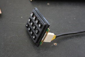
4. Then repeat 7 times for each of the 7 wires, clothe all 7 wires in some heat-shrink tubing, and then insert each of the 7 crimped terminals into the crimp housing:
5. And this is the result:
The Wiring
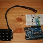
This is the wiring I used.
The green wires from arduino pins 2-4 go through to the three columns (pins 1, 3 & 5 on the keypad).
The blue wires receive the data from the rows. The blue wires go into arduino pins 5-8 and are wired to the keypad’s pins 2, 4, 6 & 7. The only wrinkle is to make sure that each input has a pull-down resistor going to ground (see the resistors going out on each blue wire). These make sure that the blue input wires don’t give false positives.
The Sketch
See comments in the sketch for full explanation.
Basically this sketch fires each column in turn, and when each is fired it reads the rows to see if anything has been pressed: if a column is fired, and a key is pressed, then the row corresponding to the key will record a positive, knowing which column it was and which row recorded the ‘high’ you can know the key.
/*
Matrix Keypad Sketch
Created by ben @ Cape Ealing
*/

// This sketch powers HIGH each of the keypad columns in turn.
// In other words, set Column 1 HIGH (for nos 1, 4, 7, #),
// then Col2 (2, 5, 8, 0), then Col3.
// When each one is set, it reads the Rows to see which
// (if any) is getting an input.
// Knowing the Column and the Row, it knows the result.


// So begin by defining a reference for each column.
// Column 1 comes out of Pin 3 on the keypad so it's called Col1Pin3.
// Col1Pin3 is wired to Arduino digital pin 2
int Col1Pin3 = 2;
// Col2Pin1 is wired to Arduino digital pin 3
int Col2Pin1 = 3;
// Col3Pin5 is wired to Arduino digital pin 4
int Col3Pin5 = 4;

// This variable records which column is being 'fired'.
// the first column is wired to arduino pin 2 (see Co11Pin3 above)
int Col = 2;

// When each keypad column is fired HIGH, the arduino
// the reads the keypad rows.
// Naming convention as above, Row 1 comes out of Pin 2 on the keypad (Row1Pin2)
// Row1Pin2 is wired to arduino digital pin 5
int Row1Pin2 = 5;
int Row2Pin7 = 6;
int Row3Pin6 = 7;
int Row4Pin4 = 8;

// Each row must have a corresponding variable which will
// store whether it was 'high' or 'low'.
int Row1Pin2Val = 0;
int Row2Pin7Val = 0;
int Row3Pin6Val = 0;
int Row4Pin4Val = 0;

// Another variable has to hold result of the scan (which row it was)
int Row =0;

// combining row and column data gives the result
int Result =0;

void setup() {

  // set up the columns to digital output pins
  pinMode(Col1Pin3, OUTPUT);
  pinMode(Col2Pin1, OUTPUT);
  pinMode(Col3Pin5, OUTPUT);

  // start the serial communication
  Serial.begin(9600);
}

void loop() {

// Send power through each of the 3 columns in turn
// Read all the rows when a column is 'high'.
// Knowing which column was high, when the row receives an input
// You know which key was pressed
// the do...while loop sets each column high in turn
do
{
  // set the relevant Column high
  digitalWrite(Col, HIGH);

  // read the value on the analog pins
  Row1Pin2Val = digitalRead(Row1Pin2);
  Row2Pin7Val = digitalRead(Row2Pin7);
  Row3Pin6Val = digitalRead(Row3Pin6);
  Row4Pin4Val = digitalRead(Row4Pin4);

  // See if any of the rows show that a key had been pressed

  //Row 1 has been pressed
  if (Row1Pin2Val ==HIGH){
  Row=1;
  Result = Row + Col -2;
  }

  //Row 2 has been pressed
  if (Row2Pin7Val == HIGH){
  Row=4;
  Result = Row + Col -2;
  }

  //Row 3 has been pressed
  if (Row3Pin6Val == HIGH){
  Row=7;
  Result = Row + Col -2;
  }

  //Row 4 has been pressed
  if (Row4Pin4Val == HIGH){
  Row=10;
  Result = Row + Col -2;
  }

  // return the column to low
  digitalWrite(Col, LOW);
  // move to the next column
  Col++;

  // repeat until gone through all 3 columns (ie: 2, 3, 4)
} while (Col<5);

// report the results of the scan if a key was pressed
if (Result>0){
  Serial.print(Result);       // prints the key value
  Serial.print(' ');       // prints a space
  delay(250);
}

// reset the variables
Col=2;
Row=0;
Result=0;

// return to the begining of the loop
}
The Output
 The output from the sketch is shown on the right.
Next steps
That’s the last of the individual components done (stepper motors, bluetooth, arduino on a breadboard), now time to put them all together in a full working prototype to test with the ASCOM driver (ie the laptop end of the project).
Ben


post a comment...
you must be logged in to post a comment.