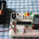
so this was an important day….
the set up runs as follows:
1. the visual basic (Vb.Net) application sitting inside the skymap programme sends out a line of data over bluetooth
2. the atmega168 chip, which was programmed on an arduino diecimila board and is now sitting on a separate breadboard, powered by battery, with a bluetooth (bluesmirf) chip attached to it, receives that line of data via bluetooth.
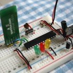
3. the atmega168 chip flashes 3 LEDs according to the data received from the visual basic programme.
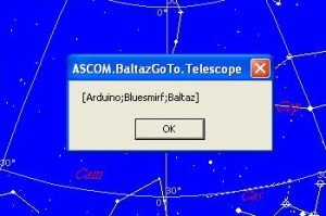
4. the atmega168 then sends a message back to the laptop (well, the visual basic programme running on the laptop) saying the programme has completed.
5. the visual basic programme then displays the message it has just received in a message box.
so, completely wireless communication between visual basic programme on laptop and atmega168 chip.
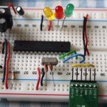
now it will be pretty simple to programme that chip to do more useful things – like move two stepper motors – one in azimuth, the other in altitude according to instructions sent out from the visual basic programme.
eureka.
the wiring is shown on the right and below:
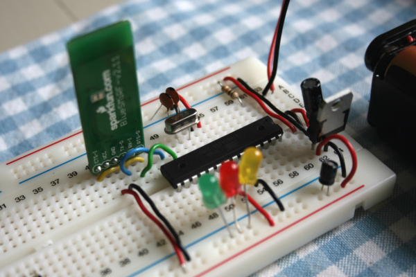
i had to keep an eye on the pin-mapping.
My first ‘test sketch’ was the one which uses the VB.Net application (sitting in SkyMap Pro) to send the following data via serial: “[15;10;5]”.
The VB.Net code is as follows:
Public Sub BG_LiveConnect()
    '''''''''''''''''''''''''''''''''''''''''''''''
    'Connect 'live' to Baltaz via the Serial Port.'
    ' '
    '''''''''''''''''''''''''''''''''''''''''''''''
    '
    On Error GoTo ErrorHandler
    If BGCserialPort.IsOpen = False Then
        With BGCserialPort
            .PortName = "COM8"
            .BaudRate = 9600
            .DataBits = 8
            .Parity = IO.Ports.Parity.None
            .StopBits = IO.Ports.StopBits.One
            .Encoding = System.Text.Encoding.ASCII
            .ReadTimeout = 5000
        End With
        BGCserialPort.Open()
    End If
    BGCserialPort.Write("[15;10;5]")
    Exit Sub

ErrorHandler:
    Call BGCError()

End Sub
Another bit of VB.Net code sitting inside the skymap programme waits to see if anything is received by the laptop application from the serial port. If it receives a “[” it gathers the message, ie until it receives a “]”, and then displays that message:
''''''''''''''''''''''''''''''''''''''''''''''''''''
'SerialDataReceived Event '
'This event runs when the serial port receives data.
'
''''''''''''''''''''''''''''''''''''''''''''''''''''
Private Sub Receiver(ByVal sender As Object, _
ByVal e As System.IO.Ports.SerialDataReceivedEventArgs) _
Handles BGCserialPort.DataReceived
    'Declare the variables for the code
    Dim RxChar As Char
    Dim RxMessage As String
    'Empty the variables
    RxChar = ""
    RxMessage = ""

    'While there is data to read...
    While BGCserialPort.BytesToRead > 0

        'Store each character received and concatenate
        'to form a single message
        Do
        RxChar = ChrW(BGCserialPort.ReadByte)
        RxMessage = RxMessage & RxChar
        Loop Until RxChar = "]"
    End While

    'Show the message
    MsgBox(RxMessage)

End Sub
Next, the programme sitting on the slightly smaller computer (the atmega 168 chip). The sketch is below (it’s the same an earlier posting), as you can see the chip reads the data it receives between two square brackets, and then flashes the LEDs accordingly. So, “[15; 10; 5]” will flash Pin 11 x 15, Pin 12 x 10, Pin 13 x 5.
Once the chip has flashed the LEDs the appropriate number of times, it sends the following line back to the PC / laptop over bluetooth: “[Arduino;Bluesmirf;Baltaz]”. This text will be read in the VB.Net application and displayed in a message box.
The sketch:
/* AFSoft Serial Mode - Multi-Bits
 * ---------------------------------------
 *
 * Turns on and off an LED on Pin 13 according to the number
 * transmitted to the arduino via the bluesmirf.  Can now
 * receive a number larger than 1-bit.
 * Sending [5;10;15] will: flash Pin 11 x 5, Pin 12 x 10, Pin 13 x 15.
 *
 * Then this sends out a single message "[Arduino;Bluetooth;Baltaz]"
 *
 * Acknowledgements
 * The difficult serial parsing bit was came from Nition
 * see forum post at:
 * http://www.arduino.cc/cgi-bin/yabb2/YaBB.pl?num=1203538464/2#2
 *
 * The AFSoftwareSerial library came from ladyada.  It adds the
 * serial.available functionality.
 * download it here: http://www.ladyada.net/make/eshield/download.html
 *
 * created 25 June 2008
 * by Ben
 */


// include the AFSoftSerial library
#include <AFSoftSerial.h>

// define the pins on the arduino:
// pin 2 on arduino (to receive) connects to tx-0 on the bluesmirf
// pin 3 on arduino (to transmit) connects to rx-1 on the bluesmirf
// pins 11, 12 and 13 to flash

#define rxPin 2
#define txPin 3
#define flashxPin 11
#define flashyPin 12
#define flashrPin 13

//define the variables for parsing serial data
#define tagLength 6	// each tag ID contains 6 bytes
#define semicolon 0x3b   // ";" semicolon
#define dataRate 9600    // 9600kbps
#define leftbracket 0x5b // "[" left squarebracket
#define rightbracket 0x5d // "]" right squarebracket

int tagIndex = 0;		     // counter for number of bytes read
int allComplete = false;	    // whether all tags have been read
char xVal[tagLength], yVal[tagLength], rVal[tagLength];
int xComplete = false;
int yComplete = false;
int rComplete = false;

// set up a new serial connection using pins 7 and 6
AFSoftSerial mySerial =  AFSoftSerial(rxPin, txPin);

// the setup part of the script
void setup()  {

  // define pin modes for tx, rx:
  pinMode(rxPin, INPUT);
  pinMode(txPin, OUTPUT);
  pinMode(flashxPin, OUTPUT);
  pinMode(flashyPin, OUTPUT);
  pinMode(flashrPin, OUTPUT);

  // set the data rate for the serial port
  mySerial.begin(dataRate);
}

// the main part of the script
void loop() {

  // read in and parse serial data:
  if (mySerial.available() > 0) {

  //just put in a loop here
    delay(1500); // wait for all data to be in. 1500 works fine.
    readData(); // read the data that's been received

  // flash the Pin 11 [xVal] number of times
    for (int a=0; a<atoi(xVal);a++){
    digitalWrite(flashxPin,HIGH);
    delay(100);
    digitalWrite(flashxPin,LOW);
    delay(100);
    }

  // flash the Pin 12 [yVal] number of times
    for (int a=0; a<atoi(yVal);a++){
    digitalWrite(flashyPin,HIGH);
    delay(100);
    digitalWrite(flashyPin,LOW);
    delay(100);
    }

  // flash the Pin 13 [rVal] number of times
    for (int a=0; a<atoi(rVal);a++){
    digitalWrite(flashrPin,HIGH);
    delay(100);
    digitalWrite(flashrPin,LOW);
    delay(100);
    }

  // run the DataComplete procedure
    DataComplete();

//End: If Serial.Available > 0
  }
//End: loop
}

void readData() {

// Reset all the variables
    xComplete = false;
    yComplete = false;
    rComplete = false;

    for (int i=0;i<5;i++){
    xVal[i] = 0x00;
    yVal[i] = 0x00;
    rVal[i] = 0x00;
    }

// Read the serial data
char thisChar = mySerial.read();

 if (thisChar == leftbracket){
   // read all x
  while (xComplete == false && mySerial.available() > 0){
    	char thisChar = mySerial.read();
   //   Serial.println("x-loop");
	if (thisChar == semicolon){
  	  xComplete = true;
	  break;
	}
	else {
  	  xVal[tagIndex] = thisChar;
	  tagIndex++;
	}
  }
  tagIndex = 0;

 // read all y
  while (yComplete == false && mySerial.available() > 0){
	char thisChar = mySerial.read();
   //   Serial.println("y-loop");

	if (thisChar == semicolon){
	  yComplete = true;
	  break;
    }
	else {
	  yVal[tagIndex] = thisChar;
	  tagIndex++;
	}
  }
  tagIndex = 0;

 // read all r
  while (rComplete == false && mySerial.available() > 0){
	char thisChar = mySerial.read();
   //   Serial.println("r-loop");

	if (thisChar == rightbracket){
	  rComplete = true;
	  break;
	}
	else {
	  rVal[tagIndex] = thisChar;
	  tagIndex++;
	}
  }
  tagIndex = 0;

  if (xComplete == true && yComplete == true && rComplete == true){
    // Can put in debugging here
  }
 }
}

void DataComplete(){
  // after all the data has been received and the LEDs flashed...
  mySerial.print("[Arduino;Bluesmirf;Baltaz]");
}
This is the final screenshot which shows that the chip has successfully run its programme and sent back the following message over bluetooth:
magic.
T


post a comment...
you must be logged in to post a comment.