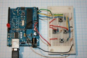
capeMirror also needs to be controlled using ‘on-board’ controls (up, down, left, right). Fortunately, it proved pretty easy to programme the Arduino to do this – although this excellent tutorial helped. The tricky bit was the wiring.
The Wiring
 The wiring can be seen on the right. There are four push buttons wired into analog pins 0-3 on the Arduino. The Arduino reads the input on these pins. The pins are analog pins so they don’t just HIGH or LOW but instead a figure between 0 and 1023. (There is a good short tutorial on using Arduino analog pins here.) I used the analog pins because the other digital pins are going to be used by the stepper motors etc.
The keypad gets its power on the rails on the left (+ 5v) and right (ground). Basically, when any button is pressed (more than one can be pressed at a time) the power runs through the button, through the smaller of two resistors (ie the blue resistors in the picture not the brown ones), to the analog pin on the Arduino.
The trick, though, is when the button is not pressed. This is where one ‘pull down’ resistor (the brown ones with brown black red gold bands – each 10K) is needed per input pin. These are needed because you can’t simply leave a pin ‘floating’ – ie neither + 5volts nor nothing. If left ‘floating’ then the pin returns wierd unpredictable results. To avoid that, any spare electrons that might be ‘floating’ around and causing the anomolous readings have to be channeled down to ground. That is where the larger resistors come in. They are used when there is no formal current running through the button to the pin. In that case, any excess charge is ‘pulled down’ to ground. The tutorial explains it better!
When there is current flowing then the electrons take the ‘easier path’ through the small value resistors (the blue ones) and go to the input pin. The current doesn’t bypass the pin and go to ground because of the massive 10k resistor ‘blocking’ it’s path. The other resistors in blue packaging are much lower value resistors. They just protect the pin when the 5v is running to it. They ‘take the edge off’ the current. Again, the tutorial explains it all much more clearly!
The Sketch
With that wiring, time to programme the Arduino. This sketch just flashes an LED according to whichever button has been pressed:
Up: 1 flash
Down: 2 flashes
Left: 3
Right: 4
/*
Keypad test programme
by Ben
*/

// define the buttons
// pin 0 wired to the Down button
#define switchPinDown 0
// pin 1 wired to the Right button
#define switchPinRight 1
// pin 2 wired to the Up button
#define switchPinUp 2
// pin 3 wired to the Left button
#define switchPinLeft 3

// define the polling delay for the buttons
#define ButtonPollDelay 250

// Pin 13 is an LED
#define LEDPin 13

// define the variables that will store the data from the buttons
int UpBtnVal = 0;
int DownBtnVal = 0;
int LeftBtnVal = 0;
int RightBtnVal = 0;

// integer to hold number of times to flash pin
int FlashTimes = 0;

// no setup needed
void setup()
{
}

// the main programme loop
void loop()
{

// poll the 4 buttons to see if any pressed
UpBtnVal = analogRead(switchPinUp);
DownBtnVal = analogRead(switchPinDown);
LeftBtnVal = analogRead(switchPinLeft);
RightBtnVal = analogRead(switchPinRight);


// Read the value of each analog pin
// anything over 500 (these are analog pins) counts as
// a button that's been pressed

// check the up button value
if (UpBtnVal > 500){
FlashTimes=1;
}  // end if up

// check the down button value
if (DownBtnVal > 500){
FlashTimes=2;
}

// check the left button value
if (LeftBtnVal > 500){
FlashTimes=3;
}

// check the right button value
if (RightBtnVal > 500){
FlashTimes=4;
}

// Flash the buttons as required
for (int i=0;i<FlashTimes;i++){
digitalWrite(LEDPin, HIGH);  // LED left on
delay(500);
digitalWrite(LEDPin, LOW);  // LED left on
delay(500);
}

// re-set the variable
FlashTimes=0;
}
Ben
Post script
In the event, I decided to upgrade the keypad on the mount to a matrix keypad (ie one with 1-9 and *, 0, #). These are harder to wire. But full details are in this post.


post a comment...
you must be logged in to post a comment.