So this is the ‘brains’ of the mirror mount. or at least this is the gadget used to programme those brains. it’s an arduino (pronounced: “aard-ween-oh”), as if you hadn’t guessed.
a v brief intro
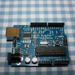
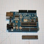
the arduino is a small electronics board which houses a removable chip (an “ATmega168” ie 168 kb of memory) on to which you can load your own programmes via a USB connection. The pictures above show (i) the arduino itself and (ii) the arduino with its ATMega168 chip removed . On the right, is a pin-map showing how the arduino uses the 28 ATmega pins – you can see there are 14 digital pins (they can input / output digial info – ie HIGH/LOW), 6 analog input pins that can read a sliding scale of voltage input, and 8 pins needed to support the chip.
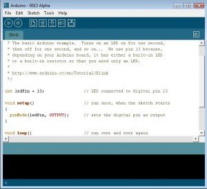
As for programming, the software for the board is all open source and you write programmes (or ‘sketches’) in a variant of C++ (see the image of arduino coding environment below).
The idea is to programme the chip to receive commands from a laptop (via bluetooth) and then move the two stepper motors accordingly. in time, it might get a bit more advanced – for example having direct ‘user control’ via a keypad as well as receiving instructions from a laptop.
I stumbled across the arduino having spent hours surfing to find some way of programming a small chip that could be used to control mirror mount. this was by far the cheapest and easiest way of doing it. and the arduino seems to have a band of intruiging followers many of whom use this chip for art installations and other experiments in ‘physical computing‘.

check out ‘freeduino‘ for a useful summary of arduino-related resources.
I bought mine (an arduino diecimila) here but if I were getting one today I would agonise for hours about whether I should get one of these instead – an arduino nano. v nice. v small, but you can’t remove the chip.
Having downloaded the software (get the latest version here), it’s time to write a programme (sketch) and upload it onto the board. The IDE (integrated development environment) can be seen above. It basically comprises a programming section (here the starter ‘blink sketch’) with a message area at the bottom (the black section) which shows results from the chip (if it’s reporting data back) or general information about the progress of uploading sketches to the chip etc.
the blink ‘sketch’ programmmes the chip as follows:
/*
 * Blink
 *
 * The basic Arduino example.  Turns on an LED on for one second,
 * then off for one second, and so on...  We use pin 13 because,
 * depending on your Arduino board, it has either a built-in LED
 * or a built-in resistor so that you need only an LED.
 *
 * http://www.arduino.cc/en/Tutorial/Blink
 */

int ledPin = 13;                // LED connected to digital pin 13

void setup()                    // run once, when the sketch starts
{
  pinMode(ledPin, OUTPUT);      // sets the digital pin as output
}

void loop()                     // run over and over again
{
  digitalWrite(ledPin, HIGH);   // sets the LED on
  delay(1000);                  // waits for a second
  digitalWrite(ledPin, LOW);    // sets the LED off
  delay(1000);                  // waits for a second
}
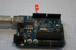
Having written that code you then (i) compile it; and (ii) upload it to the arduino board. Once on the board the chip is programmed and in this example will then flash an LED on pin 13 – as below.
A cautious start.
Ben


post a comment...
you must be logged in to post a comment.